|
Home |
|
Contact |
|
Service List |
|
Project List |
|
Publications |
|
Other Material |
|
Related Links |
|
This page contains further pictures and notes relating to E-class amplifier designs and other amplifier structures. |
|
Overview and pictures of initial test setup for 13.56 MHz 1kW E-class source |
|
Other E-Class amplifier information |
|
For more information: |
|
E-mail: martin_at_mjb-rfelectronics-synthesis_dot_com |
|
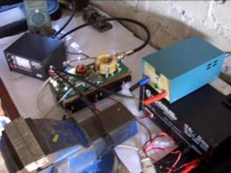
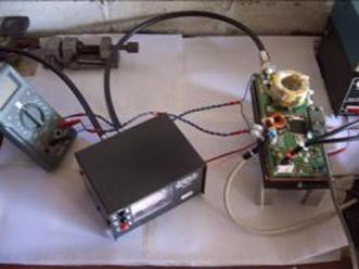
Initial testing and tuning of the source was carried out using the following equipment. PSU: Main supply: 12A Isolation transformer + various RCD and thermal trip circuits + 10A open frame variac with a rectified and capacitively smoothed output. Gave approximately 0-300 VDC output. Driver supply: 8A, 12V Linear power supply. Low voltage Supply: For oscillators and low power source — 1A, 5V linear power supply. Note: Pictures show the “Risky” open-frame variac with “tupperware” insulation. The variac was later changed to a closed frame unit, and completely enclosed. RF Load: Initially a modified oil-filled “Cantenna” was used. Water cooling, air cooling and modification of the input connectors and coax was carried out. Initially the PL259 connectors were used, however long-term operation tended to melt the dielectric in the connector and coax. RG213 coax was used for all high-power output connections. Consequently, some custom N-type connectors were made with ceramic dielectric at the load end. Unfortunately I didn't take any pictures of the load set-up, but I may try and take them at some point. Note: Later on a Bird water-cooled 50kW load was also used as a load.. Monitoring: Initially, to aid tuning, I used some older low-frequency equipment for monitoring the drain-source voltage, and the RF output. For drain-source monitoring, the amplifier circuit had an integrated capacitive divider (10:1) on the drain connection of the amplifier MOSFET. This allowed monitoring to be carried out with a conventional 10:1 oscilloscope probe, if required. A 100:1 high-voltage probe was also used for monitoring at this point. This probe was primarily used in conjunction with an old TDS210 60MHz oscilloscope. During operation, RF output power and VSWR was initially measured with an inline VSWR meter. In addition, to monitor the output signal a Bird 4275 inline sampler (set to 60dB attenuation) was used in conjunction with an HP8557A spectrum analyzer. Later power / VSWR measurements were made with a Bird 4421 power meter Various other equipment, such as, thermocouple meters, IR thermometers, and multi-meters were used to monitor temperature, current and voltage during operation. In addition , later testing used the safety-cutout unit (outlined on the projects page) to automatically shut down the circuit in case of over temperature, over voltage and other abnormal operating conditions. Note: during operation a “Chicken Stick” was also used — Basically a 1 metre long acrylic tube with a grounded metal spike at the end. This allowed quick discharging of components in the test setup. |
|
MJBRF-Electronics Dr. Martin John Burbidge |
|
Electronics and RF, research, development and prototyping. |
|
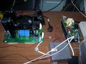
Initial test setups with safety cut-out unit |
|
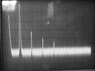
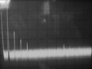
Left-hand output spectrum plot 1kW operation: Span 100 MHz (10MHz/div), 10dB/div, RBW 1MHz. Fundamental 1st Harmonic: 13.56 MHz at 0dBm, monitored via inline sampler (i.e 60dBm out of RF source). 2nd Harmonic: 27.12 MHz at approximately –32dBm Right-hand output spectrum plot: This is the same as above but with the span set to 200 MHz. |
|
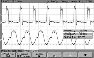
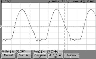
The left-hand plot above shows the pulse signal to the gate drive circuit (top trace) and the actual gate drive signal (bottom trace). The right-hand plot shows the drain waveform. Note that the Pk-Pk voltage indicated is 53.09 V, this as to be multiplied by 10 to give the actual voltage as 531 V. Measurements' were taken using an Agilent 5621D Oscilloscope. |
|
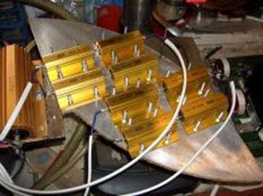
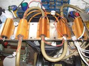
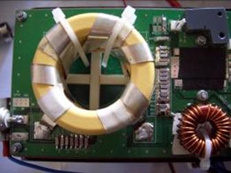
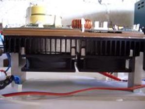
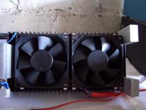
Heat-sink arrangement and fans for E-class source |
|
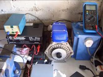
System setting up prior to operation with custom SMPS (see Projects page as well) and various resistive loads used to test the PSU unit. |